Sunday, February 17, 2019

Final Lecture/Lab Post

2/14/2019

FINAL - Lecture Portion (5% of class grade)
To receive full credit on the lecture portion of the final you must create a final blog post speaking about the final project/competition of the class.

Your blog post should include the following:
(Be sure to include pictures and/or videos to accompany the following as well)
1. A description of the final competition requirements.
2. Describe how you approached the competition and whether your method worked.
3. Changes that you made to your initial approach.
4. What you learned from the final project.
5. What you would do/change if you had more time to be more competitive in the final project.
6. What things you think you will take with you from this class and how you might apply it in the future.
7. Copy and paste of the Final code you used for your robot.

Your blog post will be graded based on the overall quality and inclusion of the above criteria as well as how in depth you go.

------------------------------------------------------------------------------------------------------------------------
1. Copied for lab handout
A description of the final competition requirements.

Rules for Fire Fighting Competition

The objective is for the robot to locate and extinguish the candle in the minimum amount of time. The robot score is essentially the time (in seconds) required for the robot to locate and extinguish the candle.
1.       A single lit candle is placed in one of the 4 rooms of the maze. The robot will begin at a starting point and once the robot begins to move the time will start.
2.       There will be 3 rounds in which each robot is allowed 2 attempts per round to locate and extinguish the candle. The better of the 2 attempts per round will be counted.
          Round 1 – You can pick which room you want the candle placed in.
          Round 2 – You will be told which room the candle will be placed at least 15 minutes in ahead of time.
          Round 3 – The candle will be placed randomly in one of the rooms.
3.       A robot that successfully extinguishes the candle in more than one round will receive a final score equal to the average of the times of the successfully completed rounds. Robots that successfully extinguish the candle three times will be rated higher than robots with only one or two successful runs, regardless of the run times. A robot that extinguishes a candle in a higher round will be rated higher than a robot that extinguishes the candle in a lower round.
4.      There is also a room factor that is applied to your overall time from start to extinguishing the candle. You do not need to go into the room to consider it “explored.” Just driving by its entrance will consider that room explored.
·      Candle found in first room explored ——– 1.0 factor
·      Candle found in second room explored —– 0.85 factor
·      Candle found in third room explored ——– 0.50 factor
·      Candle found in fourth room explored ——- 0.35 factor
5.       There is a bonus for returning to the home position after extinguishing the candle. If a robot can return to within 5 inches of its starting point, after extinguishing candle, the extinguishing time is multiplied by a factor of 0.8
6.      In any round you elect an arbitrary start position that is randomly selected, the extinguishing time will be multiplied by a factor of .8

Rules

1.       Robots must be constructed and programmed using Vex Basic Robotics Kits and all other materials must be approved by the instructor.
2.       Robot maximum size is limited to 14 inches by 14 inches by 8 inches. No sensor can be higher than 10 inches from ground.
3.       The robot must move to within 12 inches of the candle before the robot extinguishes the candle.
4.       The robot is not permitted to “look” over the walls of the maze.  The robot is not permitted to climb over the walls of the maze. The robot is permitted to touch the walls at any time during the run (with no penalties).
5.       The robot is not permitted to touch the candle in any way when the candle is lit except with a designating extinguishing device, otherwise there is a 1.5 times factor applied. There is no penalty for touching the candle after the candle is extinguished. The extinguishing device cannot be in operation more than 10 seconds during entire search.


Arena Details


1.       Arena is 8ft by 8ft. The walls of the arena are 12″ +- 1″ in height. The walls are made of 3/8″ mdf. The floor of the arena will be the default flooring of the classroom (a commercial floor tile).
2.       The maze dimensions and layout are known prior to the contest. Any dimension may vary by up to an inch of the labeled value.
3.       There is a circle constructed from black electrical tape on the floor at the fixed home start position. The robot must be completely inside the start circle, but can be faced in any direction.
4.       The candle will be placed at least 3 inches away from any wall.  The candle will not be positioned at the entrance of the room. In all cases, the robot will be able to enter the room (12 inches minimum) without making contact with the candle.
5.       The height of the lower portion of the flame is roughly 3 inches from surface.
There will be black lines of tape at the entrance to the rooms.

2. Describe how you approached the competition and whether your method worked.  AND
3. Changes that you made to your initial approach.

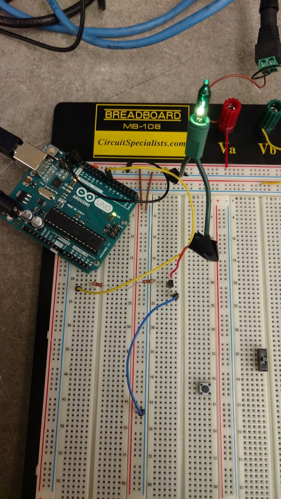
We approached the competition with a plan. Our methods worked on timing,  but the draw back was sensors. Our method is great, but for a perfect world. The logic was all there, but the error was a big result on sensors accuracy. The IR sensor has arbitrary values that changes very dramatically with the light in the room. Shade and even a cover will greatly change the results. The UltraSonic Sensor was a different chapter. The sensor that we had had random numbers occasionally pop up. We switched it out for another ultraSonic Sensor, but after lots of trials and tuning, ir turns out that that sensor was just faulty in inoperational. We installed another UltraSonic Sensor (our 3rd one) and that one worked. It still popped out a few random numbers of error, but it was less common than the initial sensor unit. The encoders worked great, till they somehow got some dirt inside, then errors came out. A smile dust out clean cleared out the sensor. We used to have full power to motors for speed, but we changed the approach by reducing power to the wheels, so there was less wheel slip on the ground surface. The encoders was only as accurate as the wheels having traction on the competition floor, which by the way was a bit slippery.

4. What you learned from the final project. 

Lots was learned, especially that robotics competition or even the robotic build is very possible in our homes. The sensors are able to be purchased and even sold in a bulk pack. Each unit is easily programmed with easily accessible and downloadable programs. Coding has been done or you can research and modify others code. Simply making code from scratch has such a deep gratifying experience and a sense of accomplishment. We did our program from scratch and it worked out great as used lots of functions in our approach.

5. What you would do/change if you had more time to be more competitive in the final project

If we had more time, we would have perfected the code. The biggest change would have been the realignment technique. I witnessed a student in our class do it, and it was super impressive and ingenious. The technique was to have the robot move forward, but after every turn, the robot will shortly reverse itself and ram into the wall behind it. The idea is to have the robot be flat against the floor, so that each time the robot moves forwards, the bot will go exactly straight forward. It eliminates the error that accumulates with slippage error on the track surface. I would have implement that kind of alignment technique. It proved impossible to beat when combined with the reduced power sent to the wheels to prevent slippage.

6. What things you think you will take with you from this class and how you might apply it in the future.

I will for sure take programming into a whole new level with complicated functions. Not complicated, but more duplicated functions to command different tasks, makes it a lot simpler than having a giant code block. I think I am actually going to try to invest in a VEX kit. i have used it before many years ago, but I was extremely intimidated by the programming of the device. I built great robots, but severely failed on the programming aspect. It was just then a giant piece and pile of metal parts put together. I think I can actually do it at home now.

7. Copy and paste of the Final code you used for your robot.

1...2....3....Done!

Lab 17 - Using IR sensors for flame and line detection for the VEX

2/14/2019

IR sensor is able to detect IR light. As with all sensors, visible light can be detected, but thus one is able to detect InfraRed light which is light above the spectrum of visible light. Coincidentally, Android phones are able to view this light through its camera. Iphones are not able to view such light. Our robot, for testing purposes only, has been customized with a useful state of the art (in my mind. haha), an easy to grab handle. Tall hable is useful so the person, me or my robot partner, does not have to bend down all the way to grab the robot and risk getting fingers caught in the possibly still moving gears. Also useful for mounting a phone as a ash cam , and even is useful to quickly grab the robot in case the collision sensor or programming is not yet working fully properly.


IR sensor mounted


The IR sensor for this bot is going to be mounted in front of the bot because that is what is needed to be avoiding obstacles such as the walls. the sensor worked great! The only issue we found was the location in the room. In our test bench we tested the light and we were getting readings of about 500. Our bench area was not greatly lit up. The actual maze competition area, howerve, was greatly lit up by the classrooms lights. The readings in that location was much higher, and hence it was harder to see the IR candle cause of the excess light. Then problem was easily fixed by decreasing the sensitivity of the IR sensor. Since the resistor was already soldered into the sensor, we just simply changed the programming number. Project Success!

Lab 16 - Ultrasonic Rangefinder and other sensors

2/12/2019

An Ultrasonic sensor uses audio waves to detect structures such as walls blacking a path; hence rangefinder. The audio waves will signal how much open range there is that is in front of the robot. The sensor receives a 10us electrical pulse to signal the sensor to activate and send out a sound at trigger point. The Echo part will receive the audio that bounces back form the wall structure. Depending on the time it takes back for the sensor to receive the feedback, the sensor will calculate the distance away that is in front of the robot.

UltraSonic Sensor Installed

The hard part of the sensor in readings is its out of limits range. If the distance in front of the sensor is more than 6 feet away, the sensor will return a -1 value. The code for that part cant be just x>-6, the sensor for the code must also include a lower bounds limit. The key to this part of the code is to be 0<x>6. That code will ignore the -1 value and allow further distance to tell the robot to keep moving forward.

Wall Avoidance Lab
Code the lab will have the robot keep going forward unless a wall is detected. Make a right turn if a wall is detected. if a wall is detected again, move left form the original orientation; or move 180 degrees after the 2nd right turn.


Wednesday, February 13, 2019

Code.org Homework Assignment

2/5/2019

Code.org Homework Assignment

Star Wars: Building a Galaxy with CodesetBackground("Endor");
setMap("circle");
setDroid("R2-D2");
setDroidSpeed("normal");
playSound("R2-D2random");
function whenUp() {
  goUp();
}
function whenDown() {
  goDown();
}
function whenLeft() {
  goLeft();
}
function whenRight() {
  goRight();
}
addCharacter("PufferPig");
function whenGetAllPufferPigs() {
  addPoints(100);
  endGame("win");
}


SHARE GAME @  https://studio.code.org/c/140816053

Minecraft Voyage Aquatic 

for (var count = 0; count < 5; count++) {
  placeBlock("redCoralBlock");
  turn("left");
  moveForward();
  placeBlock("redCoralBlock");
  moveForward();
}

SHARE GAME @  https://studio.code.org/c/714458078


Code with Anna and Elsa
Puzzle 6 Star https://studio.code.org/c/49768924
Puzzle 9 Super Star https://studio.code.org/c/618940565
Puzzle 12 Parallelogram Star https://studio.code.org/c/51803719
Puzzle 15 Star in a Star https://studio.code.org/c/53014217
Puzzle 17 Start Star https://studio.code.org/c/618940329
Puzzle 19 Snowflake https://studio.code.org/c/53005426
Finish Star: 

for (var count = 0; count < 3; count++) {
  drawSnowflake('square');turnRight(90);
  jumpForward(100);
}

SHARE GAME @ https://studio.code.org/c/52521226


Sunday, February 10, 2019

Lab 15 - Building Square Bot and doing the Electrical Tape Maze with and without encoders

2/5/2019 & 2/7/2019

Mega bot building time! The day has come in which we will build a robot. The Robot is going to be a square on shape and it is going to go through a maze that was laid out with electrical tape. We have all the parts either in the box or in the parts room. We are basically following the manual to build the robot, but with the encoders installed in place. We are not going to use them in the first trip but we are going t use them on the second trip using the programming; just so we do not have to dismantle the bot just to install the encoders.

Bot Building Station
We worked on a side project utilizing the biggest wheels, but turning ability was terrible, so we stayed with the tiny wheels for maneuverability. 
Mega Test Bot
Due to programming constraints to one user at a time, I would periodically assist with the programming part when needed, until then I was on mechanical duty. I built the bot for the future labs too. The bot is equipped with an easy elevated carry handle so the robot can be transported easily without having to constantly be bending down to retrieve the bot or to reposition it. The bot is also rigged with some fans for blowing out a future flame, a sonar sensor upfront for the future IR detection part, and racks for video recording modularity.


Sunday, February 3, 2019

Lab 14 - Non-Existent

Nothing posted for Lab 14 on packet

Lab 13 - Building Sensors for your Robot

1/29/2019

We worked with phototransistors today in lab. It is basically a photodiode amplifier combination that is integrated on a silicon chip. Recall that a transistor has an emitter, collector, and a base pin. Notice how this device only has two actual pins. THe third pin is the base pin, which is actually  in the device already. The light (light that the sensor detects) is the base activating pin for the device. This device is going to detect IR (InfraRed). That is light that we humans cannot see, but our phones can! well, some phones; Apple phones cannot see that light, but the Android phones are able to display IR light on the camera screen.

Time permitting, we did not light a candle for flame (too messy as the wax goes onto the floors and makes a mess, and a fire hazard). We used a pre-constructed flame which is a couple of IR LEDs on a breadboard [piece that outputs IR light.

Phototransistor


Once again, due to time permits, I built a circuit on the breadboard to detect IR light. It is only one phototransistor, and One carefully chosen resistor. That resistor, depending on its value, will allow more or less voltage/current to be ran through it. The important concept in this is the preferred gain range. We want a resistor, so that when hooked up to the phototransistor, we got a high value of 1000 or so on the display with super intense IR light. The lowest we should see is around 20's when the IR light source is about 4 feet away from the sensor.


Lab 12 - Distance Sensing with Ultrasonic Sensor and Arduino

1/29/2019

Todays lab is utilizing an ultrasonic sensor. I use to thing it would just work by outputting the distance, but there is a lot more to the device than assumed. The device has 4 pins; one being a +5V power input, and the other being a ground pin. The two other pins are the controls. Order of the pins must be referred to the diagram. Third pin is a Trigger pin, that pin looks for a 10us signal pulse that basically activates the ultrasonic sensor. The sensor output s a sound wave in pulses. The last pin is an Echo pin, that pin listens for the return of the wave and outputs a pulse width proportional to the measured distance of the sensor. For simplicity of this lab, as instructed, we copied the code down for the lab/online, and just modified it to our pin setup on the arduino.


Ultrasonic Sensor/ Motor Off (no object)
                                                   

Ultrasonic Sensor/ Motor ON (object detected)
 This lab has a program, which got edited into the downloaded program, that turns ON the motor when an object is 5 inches or closer to the sensor; Motor is OFF when the sensor range of 5 inches is clear.

Alternate view
8

Sunday, January 27, 2019

Lab 11 - Microcontrollers, Input and Output

1/24/19

Microcontrollers: has an output depending on what input is received and what the command program tells the controller on what to do. A controller can receive an output such as a switch or varying resistance, in which the program will read and interpret that data. The program will then set an output (again, depending on the programming) which will produce a desired result. In this first part, we are utilizing an LDR to get a output of a number value that is representing on the amount of light in the room. That number, varying degree of light/darkness, will then be read in the controller in which  the program will turn on a certain amount of LEDs. Those LEDs are serving as light intensity indicators.
LED OFF cuz it is bright at sensor
LED ON cuz its dark at sensor


The picture below shows multiple LEDs. Varying darkness changes which and how many LEDs gets lit. Sadly the video could not fit here.


Motion Sensor
Thankfully a motion sensor was able to be installed and it operated perfectly. It outputs a +5V signal when motion is detected. All in the programming of the arduino.

Lab 10 - Using the Serial Port

1/22/19

Serial port in an microcontroller is very useful in getting values. Values, for what? There are sensors that will be connected to the analog port of the microcontroller which when given the command serial print read, the computer monitor will display the value that the microcontroller is seeing from the device connected to the port. The picture below shows a LDR (Light Dependant Resistor) that has a different resistance value depending on the amount of light that reaches the sensor, hence Light Dependant. The microcontroller on the analog port will be able to read the value, and the program can use that value to control whatever we command the controller to do.
LDR Hooked up


Serial connections has a Receive and a Transmit pin. There is also a shared pin of common Ground Reference. The arduino microcontroller in this setup will receive intel from the computer's keyboard, and transmit a command to the computer monitor and the arduino's pins. In the picture below, the computer keyboard is entered with a 1 or a 0, in which the arduino reads it, and on the code, the LED will turn either ON or OFF depending on the keyboard stroke entered. #Success


LED hooked up


Lab 9 - Driving Motors and other Output Devices

1/22/19

Controlling loads....hmmmm... how to do it with power....
A microcontroller is limited to 10mA per channel, and the whole chip  capacity is 50mA. That is not much for larger output devices. An idea is for the microcontroller to control a transistor (a power gate) to allow more current to flow to the output; rather than the power coming all form the microcontroller, the controller will control a transistor, in which power will come from the source through the transistor to the output. The transistor also has a limit, but it is much greater than 50mA. Trasnitir is rated to 200mA, that is 4 times more power than the microcontroller!
Microcontroller controlling a transistor to power a Xmas light bulb
Next step, More Power! Lets pile onto that concept. Lets have the 50mA limit microcontroller output to operate a 200mA transistor, in which that will operate a 0.6A medium power transistor....Yes! Great idea, and the microcontroller only needs about 10mA to operate such a chain, called Darlington Pairs. With this setup, we get more light out of this tiny Xmas light bulb. We will later see that all these transistors can be combined in a single package called the TO-92 package with 5A continuous max limit.


Xmas bulb with Darlington Pair
Xmas bulb with TO-92 package


PWM-Pulse Width Modulation
Control a motor with timed ON and OFF square wave pulses rather than varying the voltage. Basic attempt, and it worked! Controlled not with pure voltage, but controlled with the output of timed voltage pulses. 


PWM Controlled Motor


Saturday, January 19, 2019

Lab 8 - Bi-directional Motor Control

1/17/19

Transistors are great because you can have enough current to turn on a motor. A Circuit was designed using a tiny relay IC in which current will go into the motor and make it spin, but also have current come into the motor on its other lead to make it go the other direction. Relay is a DPDT (Double Pole, Double Throw). 


DPDT Relay circuit Schematic
H Bridge Schematic


A motor can be also controlled using a H bridge configuration. Instead of using a DPDT relay to control, the circuit, we can use an Arduino to control two transistors to allow dc current to flow in one direction, and two other transistors to have the current flow in a different path so it goes in the other way into the motor. 
DPDT Relay circuit
                           
H Bridge Circuit


Lab 7 - Introduction to Microcontrollers

1/17/19

Microcontrollers, it is a computer on a chip. It is low cost, but contains everything that is need to act a s a computer. There are many pins in which they are controlled via programming a arduino. A High state outputs a 3.3V-5V, while a Low state outputs a 0V, which is essentially off. This lab is going to be basic with LEDs. A LED turns ON when there is a High state declared on the corresponding port on the Arduino Board. Simple installation of the program was done. 1..2...3...poff...installed. Now time for programming! Downloaded program for blinking LED. Successful Blinking LED done!

Fun time with Night Rider project. Instead of just one LED, the project is with 4 LEDs that does a "scan" function that is exactly like the night rider car. I had to really review programming in loops to get this part done. Hooking up the circuit is easy, but the programming s the part that took effort. Finally got it running. Simple 220 ohm resistor was used for each LED, and each LED is designated to a single oort on the arduino.
Single LED Hookup
Program Code for Blinking LED Night Rider
Night Rider Set-up


Friday, January 18, 2019

Lab 6 - Transistor Switching


1/15/19

Transistors! huh? Transistors! They are amazing. It is a gateway for electricity. I high current can be controlled with a small current applied to its base. It is very useful for controlling a motor with a signal voltage. This lab shows the current and voltage values of different parts of a transistor in and out of operation. Parts examined includes the Base, Emitter, and Collector. The collector leads towards the Power source. The base is the controlled gateway, and the Emitter is essentially the power output to the load. Notice the picture below is using a switch; the full source voltage is triggering the base to allow current to flow to the LED.

The NPN Transistor is going to be used the majority of the time in this course. There is a PNP transistor which is the same except that the Comitter sand emitter are switched. A transistor is great to control current over a relay because hardly any current is need to activate the base. Since it is electrical, there is minimal, if any, wear. It is a lot more dependable than a mechanical relay as there are no mechanical parts to wear out. A mere 1mA, in this lab, allowed an impressive 14.1mA to flow out.

Transistor Circuit in OFF position
Transistor Circuit in ON Position


Thursday, January 10, 2019

Lab 5 - Switches and Relays

1/10/19

This lab is a nice overview on possible switches available configurations. Poles and throws were covered. Hook ups of 2 way switches was covered simply by following the wiring schematic. Relays were covered in which essentially a low power source activates a coil/solenoid, in which that will close contacts to a seperate circuit( typically a high powered circuit). This device is useful especially for controlling a high powered circuit with a low powered signal. Relay oscillator was studied and learned. It was quite amazing to hear a switch go on/off 50 times each second! That was a recipe for device destruction though. Safety precautions were observed.
Relay oscillator
Relay oscillator with a capacitor

It is worth noting that thanks to the capacitors charge/discharge characteristics, it was so much easier to see the LEDs blinking as now a time delay (or charge constant) was introduced to the circuit.


Lab 4 - Schematics, Ohm's Law and Potentiometers

1/10/19

This lab gave us quick knowledge of ground/power symbols, and schematic symbols for those inckuign the potentiometer. A potentiometer is a variable resistor, 3 terminals, 2 of which is the full resistance, while the 3rd terminal(typically in the center) is the wiper that selects a resistance in between. Experimented with LED brightness by changing the resistance. The answer is current! The voltage drop at the LED will not change, but the voltage left over must all be dissipated by the resistor. That combined with ohms law will give us current, which since this is a series circuit, will all pass through the LED. The more current, the brighter the LED will be...except of the current rating gets exceeded, then the LED will blowup....literally!
Pic above: 3 LEDs with 3 different resistors

Pic above: LED in series with a LDR


Lab 3 - Using a Multimeter

1/8/19

Lab 3 is going to be mixed a bit. I used both meters, one from the campus supply, and the other is my personal one. I like using my personal one because it doesn't have any annoying beeps and auto-shut-off noises. The plus side of the one from school is that it is auto-ranging. yay for that aspect. Meter basics of measuring voltage and current, along with continuity and the conditions was explored in this lab. Normal routine meter exercises was done in this lab from measuring DC voltage to AC voltage. Assisted student in understanding the meter and the correct probe position and selection slots.

I really liked this lab because I got exposed to the operation and characteristics of LDR (Light Dependant Resistor), Pressure Dependent Resistor, and a Thermistor (Temperature Dependent Resistor). These sensors will come in handy for robotics later (soon actually) in the semester. Quite useful to see its varying characteristics in action.


Pic above: Measuring a Size C 1.5V DC battery

Pic above: Measuring a 9V DC battery

Pic above: Measuring the 120VAC outlet with an odd number

Pic above: Measuring the 120VAC outlet with the correct value (glitch disappeared)

Lab 2 - Introduction to using a Breadboard

1/8/19

Lab 2 is about using a breadboard. I have had lots of experience with this board, so this was powered through. The lab shows how the breadboard is connected internally. Instead if making wires, I used premade wires from my backpack. #easy Resistor Color code was reviewed and how to read it. Hopefully we are not color blind. XD Used a LED in a very simple circuit to light up. LEDs are polarity sensitive. They will only light up in one direction only. Long lead to the positive side and all will be well.

Picture on Top: Breadboard with a LED in series with a resistor
Picture on Bottom: Resistor Color Code handout chart


Lab 1 - Intro to Soldering and Building Power Supply

1/8/19

Hello Fellow Blogger Reader(s)!

This is my first Blog. I will be blogging in my Mt Sac Class journey of ELEC 10 Intro to Mechatronics class that will be consisting of 17 Labs.

This lab is for soldering, which I skipped. I have many soldering practices before, and took the Soldering Class with professor Joe Denny, best professor ever! Got a pass to skip that lab due to soldering competence. Power Supply creation is a phone charger to be soldered to a wired end. That will be our 5V power supply. Since there are many in the class, they were just distributed out since soldering was skipped in lab.

Picture on Left: Soldering is easy handout in easy steps #Skip
Picture on Right: Pre-made power supply from a 5V phone charger